This is a continuation of the workflow series: part 1 and part 2.
Motivation
Have students create mathematical art in Desmos and bring that digital art into the physical world using a laser engraver. You can certainly bring any image from Desmos and engrave it into an object using a laser engraver, but this method allows you to cut out the actual line from the material so that all that is left is the shaded area.
Desmos
Create a design in desmos that has lines which are crossing at points. This method will use the laser to cut on each side of a line, so that the material “inside” the line will remain.
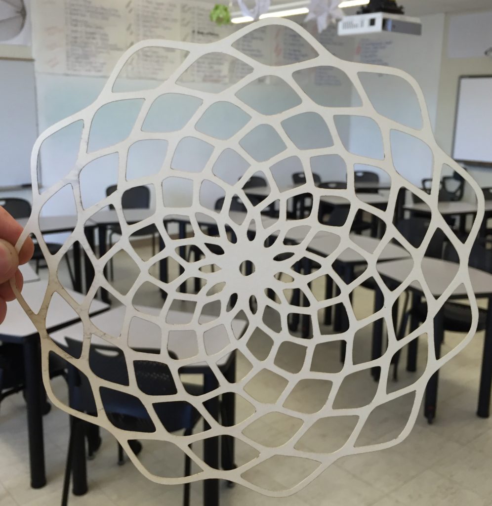
Here’s an example: Wavy Sine Circles. Turn projector mode on.
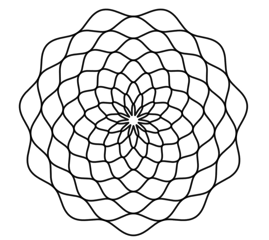
Take a screenshot of your image.
Inkscape
Open the image with Inkscape (free and open source vector image editor), and then select the image by clicking on it.
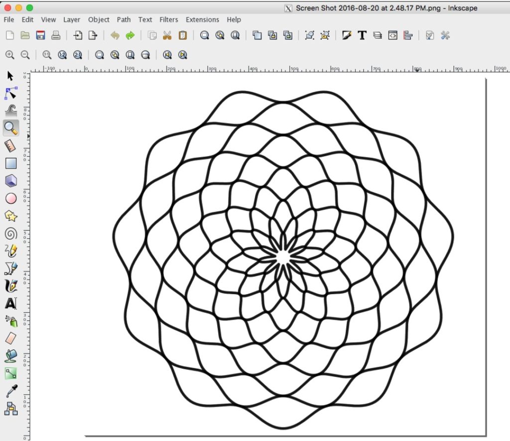
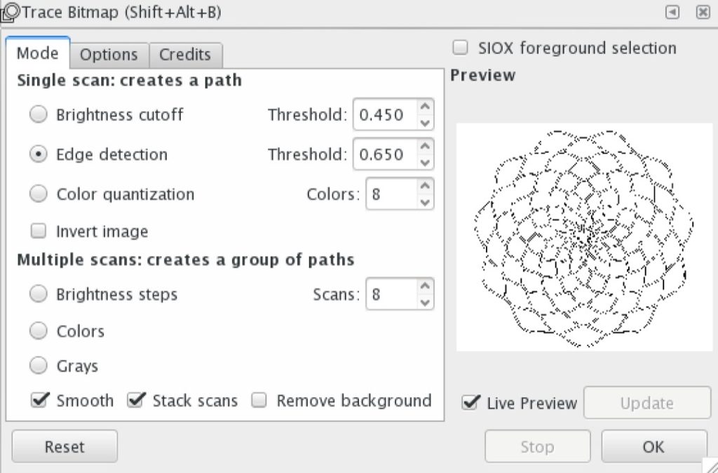
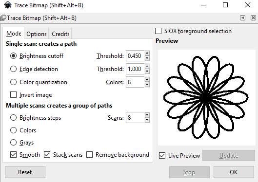
Go to Path -> Trace Bitmap.
Select Edge Detection. This selection will make vector lines on each edge of our original image.
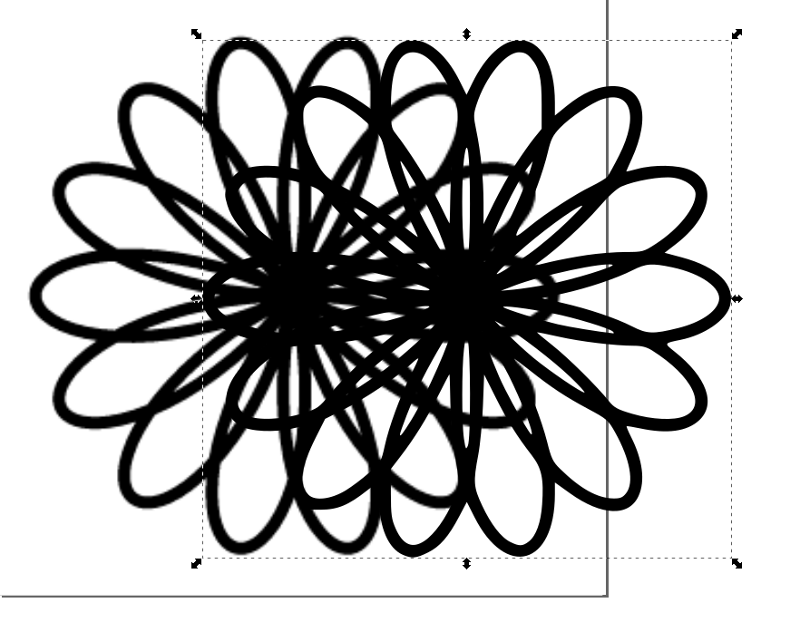
Drag one of the images sideways so that you can delete the original image and just have the vector image left.
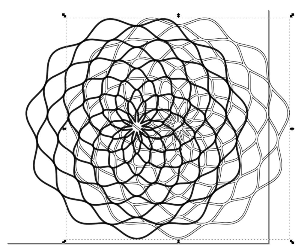
Save the vector as a .svg file so that your laser cutter will be able to follow the lines directly (Vector vs Pixel images).
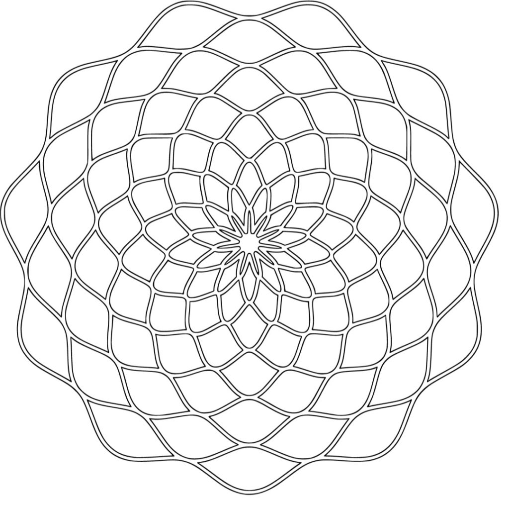
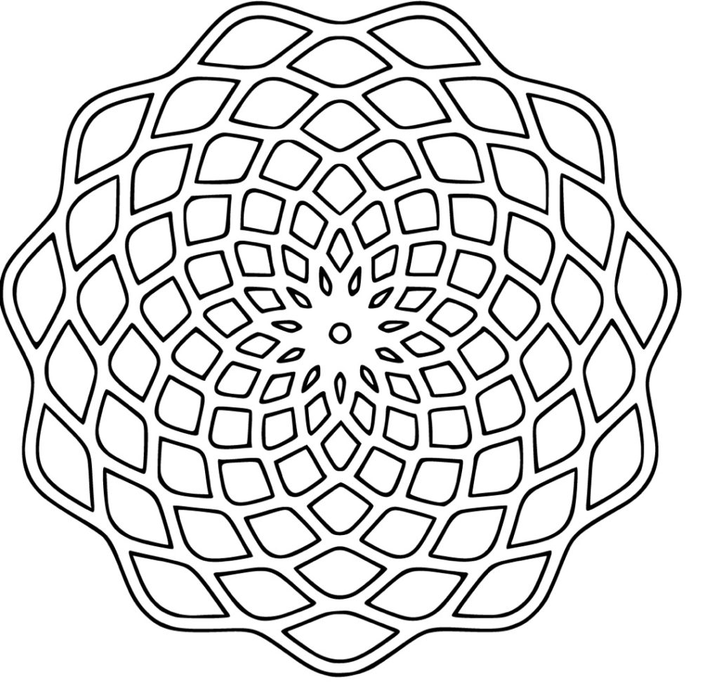
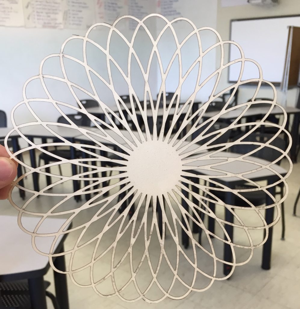
This output looks a bit “lacy” for most materials that I’d use in the laser cutter. The lines are too narrow. No problem, do the same steps with the original desmos image, but this time zoom out before you take your screenshot. Desmos will always make it’s lines a certain width, so if you zoom out, the lines will be relatively thicker. Here’s the result after a quick zoom out.
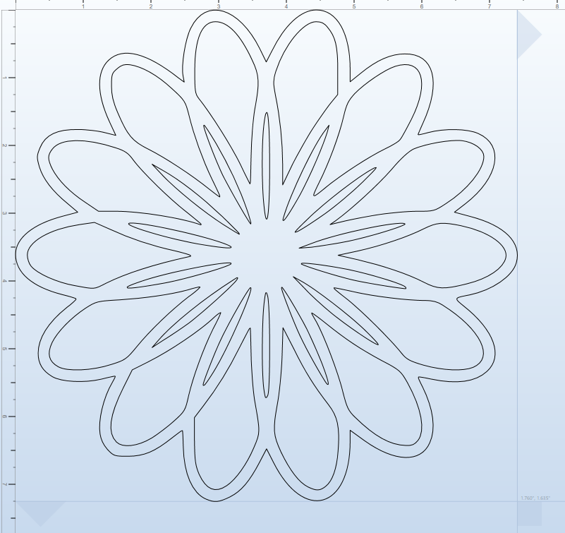
Laser Time
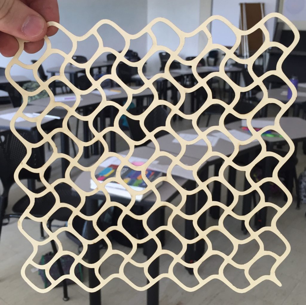
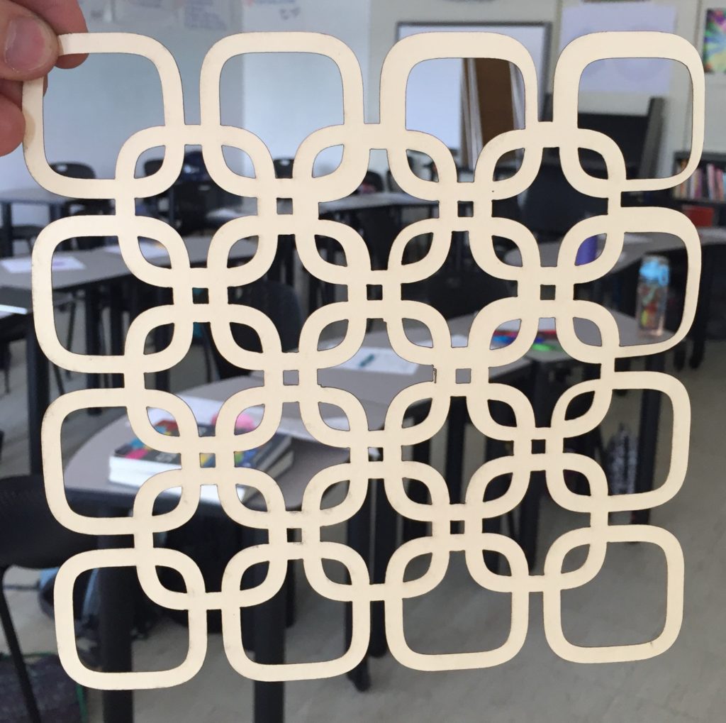
Bring your .svg file to the laser cutter that you have available (or to a vinyl sticker cutter). Here are some results (these are test cuts on manila folders):
What do you think students could make with this workflow?
UPDATE
I’ve had some trouble with the output from inkscape giving me double lines, so that the laser is making two cuts really close to each other. Here’s a fix.
When you go to trace the bitmap, keep the selection on brightness cutoff.
Result:
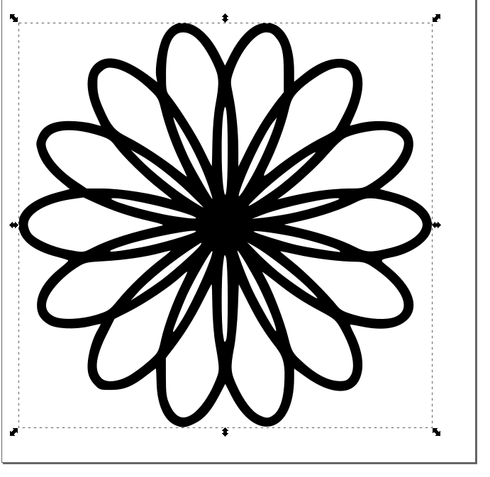
Move the vector off of the original image and delete the original image (the one that is fuzzy).
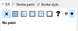
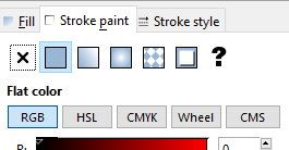
Change the fill and stroke to the following: No fill, black stroke.
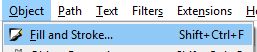
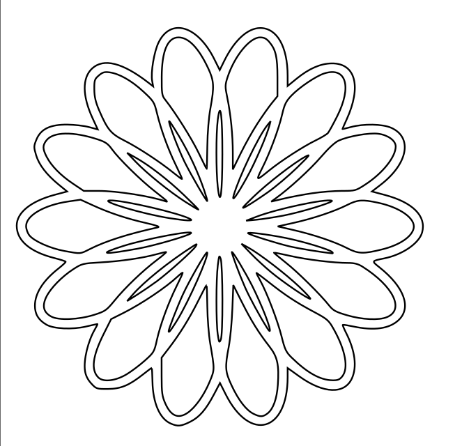
Send to your laser cutter software. Much better!